")
With the proof of concept finished, the 3-channel RC plane could then be tackled. I meticulously studied successful designs, learned of all the possible wing configurations, and practiced flying on a simulator. Construction commenced.
The materials I used were foam board and hot glue; the electronics were a transmitter and receiver, a motor, ESC, and servos. I should clarify, however, that this blog is not a direct tutorial; it simply describes the general process I followed.
The first part of construction was the fuselage.
For this, I took my foam board and cut in straight lines so that it could fold into a square prism. You will notice that throughout this process, I will make several mistakes. One of them was gluing the frame in an imperfectly shaped square. Learning can be a painful process.

I thought this wouldn’t affect its flight in any significant way, so I didn’t bother making a new one.
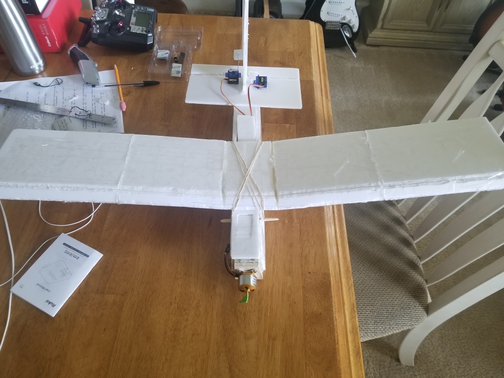
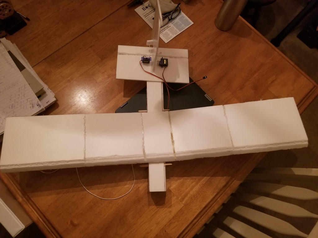
Next were the wings. For them, I cut the foam board and folded it over itself. A foam spar was under the fold and positioned near the front of it so that a leading edge could be formed. This was then hot glued a lot, incisions were made near the center of the wing (see photo), and each wing bent upward from it. This configuration is called a dihedral and helps with roll stability. (Normally, ailerons provide this control, but because I only had two servos, I opted for this solution.)
As you can see in the above photo, I made these wings very short. So short that I worried there would not be enough lift generated during flight to keep it suspended in air. As a fix, I cut short sections of wing in the manner described earlier and glued them to both ends of the wings.
Also crafted from foam board, the rudder was made in the same way as the proof of concept. That is, cut into the shape, cut down a straight line, and taped.
The elevator was simple. Simply a foam rectangle with one end turned into a flap.
The rudder was then hot glued to the elevator, which was glued to the back of the fuselage.
You probably notice electronics on this. For these, speaking specifically of the servos, I connected horns on the servos and bent paper clips, trimmed to size, to act as servo rods. The rods were pushed into the foam, and the servos were fixed to the elevator via hot glue. I should mention the rudder servo rod was pushed into a small rectangle of foam glued onto the side of the rudder (see photo).
The servos being exposed in this way will cause drag, but the reader is obligated to forgive a beginner’s first attempt. Therefore, I worry not.
The motor was next and begot the worst mistake in this construction process. To make sure it wouldn’t fall out of the plane, I created a wooden mount for it. It was sized so that it could slide in snugly. The mistake? It was so heavy!
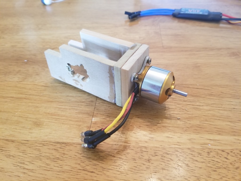
At the time, I was so comfortably ignorant that I believed this wasn’t going to be a problem. Today, having learned better, I realize my error. Moving on for now…
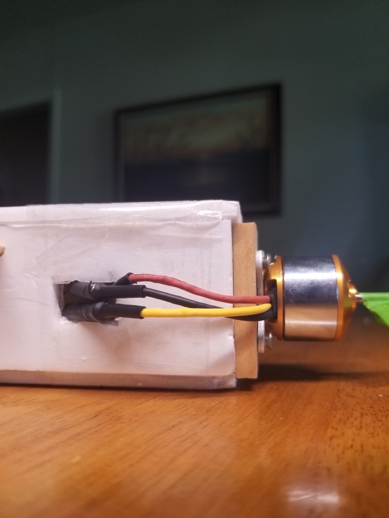
With the motor screwed on, I glued the mount in. Its upper corners were cut off to be able to slide underneath the struts, around which rudder bands loop to fasten the wing. Additionally, openings on the top of the fuselage were made so that connecting electronics wouldn’t involve rotating my hands against the movements prescribed by evolution.
One convenient feature I gave the plane was a hole in the mount that lined up with a hole in the fuselage. Through this, the motor leads could hook up to the ESC leads on the outside.
The wings were attached, the electronics connected, and… Voila!

Reinforced with packaging tape, a >250 gram plane was now finished, leaving only the exhausting process of registration for me to go through.
Since I take Latin as my world language, I named it Augustus, the first emperor of Rome. Each plane will be named after each subsequent emperor.
Ad caelum!
