
Despite my earnest pursuit of the model rocketry hobby, my efforts have been continuously undermined by the lack of one seemingly trivial thing: a launch site.
This blog will not be focusing on this regulatory struggle (though, that would make a good post). Instead, I will collate some of the interesting physics I have learned regarding model rockets. The reader may rest assured, however, that my posts about my RC plane hobby will continue shortly. (Claudius is the next plane in construction and should be lighter than Caligula, Tiberius, and Augustus.)
Center of mass (CM), center of gravity (CG), and center of pressure (CP)
Most people are familiar with CM and CG. Explained simply, these are the average locations of an object’s mass and weight, respectively. CP, however, is less commonly known and a little more complicated.
As an object moves through a fluid (e.g., air), the velocity of the fluid varies around the surface of the object. Whenever there is a difference in fluid velocity, there is a difference in pressure. The average location of pressure is called the center of pressure.
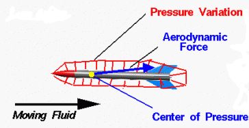
As can be seen from this diagram, the net force (called the aerodynamic force) on a rocket can be thought of as acting on the CP alone. Interestingly, the CP’s position depends on the angle of attack, i.e., on the angle it makes with airstream. The approximate rule-of-thumb describing this relationship is that, as the angle of attack increases, the CP moves toward the nose.
For rocket stability, the CP must always be placed behind the CG. This positioning will give the rocket a kind of self-correcting rotation when a nonzero angle of attack develops. Fins located near the end of the rocket help with this placement.
A reasonable question to ask is “What if the CP is in front of the CG?” Nothing good. If the rocket were to contract an angle of attack, the design would cause the angle to increase, leading to instability (and probably a destroyed rocket).
To determine whether a rocket has an optimal CP position, you can tie a string around the rocket’s CG (make sure the engine and parachute are in) and swing it around your head. If it continuously aligns with the airstream, the CP is behind the CG and no further work is needed. If it spins uncontrollably, the CP is in front of the CG and can be remedied by placing a weight near the nose of the rocket.
Alternatively, you can calculate it theoretically using the Barrowman equations. Due to their length, I have omitted writing them.
Impulse and specific impulse
Impulse, also called total impulse, is defined as the change in the momentum of an object when a force is applied to it. The greater the impulse, the greater the change in momentum. If you have studied classical physics, you will remember that impulse is equal to the force multiplied by the time elapsed. We thus have

or

You might also see this formula around:

where J is impulse, T(t) is thrust as a function of time, F is the average force, and t is the time elapsed. From this equation, you can see clearly that impulse is the area under the thrust vs time graph, a chart that can be found experimentally. Additionally, it can be seen that impulse is measured in newton-seconds (N·s), since we are multiplying force and time.
The concept of impulse is quite important in low-powered rocketry because store-bought motors are classified by their impulse. For instance, “A” class motors have an impulse of 1.26–2.50 N·s, while “B” class motors have an impulse of 2.51-5.00 N·s.
Another term you will commonly hear is specific impulse. Despite having a similar name, this concept is distinct from total impulse and is used to measure the efficiency of a propellant. It is usually described as the impulse produced per unit propellant weight. That is,

where Isp is specific impulse, J is total impulse, 
Another way of describing Isp is as the thrust per unit propellant weight flow rate:

Although it sounds like a word salad, it’s a very succinct description. In the numerator, you can see the thrust function. In the denominator, you can see the propellant mass flow rate, 

Both descriptions (impulse produced per unit propellant weight and thrust per unit propellant weight flow rate) are equivalent.
The units of specific impulse are seconds, a unit which is kind of nonsense, since you don’t actually interpret it as time. Instead, Isp can be thought as the ratio of impulse to propellant weight. Using this interpretation, if a certain propellant has an Isp of 300 seconds, one newton of that propellant will produce 300 N·s of impulse.
While Isp generally doesn’t hold any relevance to low-powered model rocketry, it frequently appears in reference to the kind of rockets that Joe Barnard builds.
The Tsiolkovsky equation
Though this equation is not used in the low-powered rocketry hobby, I think it is worthy of some dialogue.
Named after the father of modern spaceflight, this equation relates a rocket’s change in velocity to its mass and exhaust velocity.
One of its forms is

Where 


This form is sometimes more useful:

To obtain this form, simply divide both sides of the first equation by exhaust velocity and then make both sides the exponents of Euler’s number e. The natural log “cancels”.
The ratio of
In conclusion…
All of these concepts, in general, are important to rocketry (hobby-level or otherwise), but as it pertains to me, they have yet to attain their greatest use: Me applying them to build an actual rocket. The lack of a launch site, unfortunately, continuously pushes this goalpost farther into the future.
I asked the board of my local RC field whether I could launch a rocket from their property, to which they politely responded “no.” It wasn’t that they didn’t trust me, however; it was merely the fact that the FAA only allows them to fly to 400 ft. and my rocket would have gone to 600 ft. I have been considering whether I should contact a park near me to obtain permission, but I have delayed doing this, worrying that they might think I am insane.
This is not the end, however.
Ad astra per aspera!
